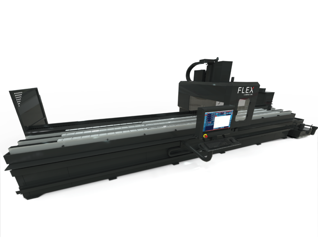
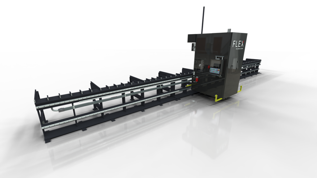
For service please call
1-800-837-2503 or
Request Service Here
Operators rely on the table for part mobility on a standard vertical machining center, limiting the maximum table load. On a FlexCNC, however, the spindle moves instead of the bed. This allows operators to work with materials or parts of any weight or size.
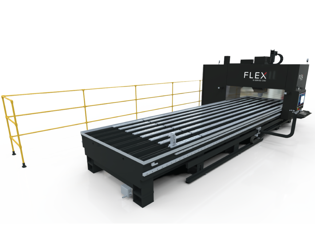
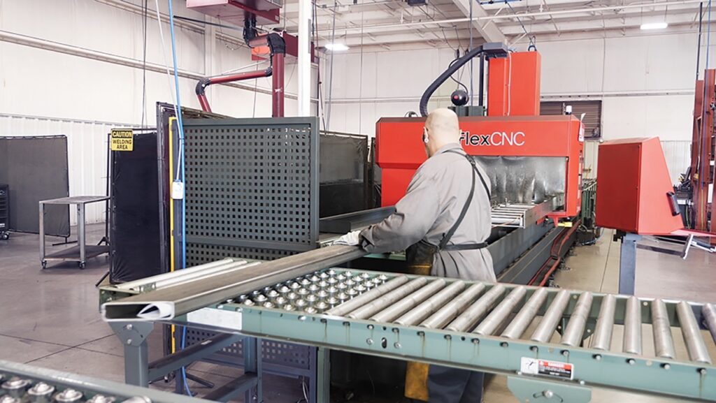
Traditional vertical machining centers require the operator to reach into the machine to load and unload parts. The open bed on the FlexCNC makes loading as simple as bringing the part over to the top of the machine and setting it down. Heavy parts are quickly loaded and unloaded with a crane or forklift.
The FlexCNC ranges in size from 10 ft to 50 ft. In addition to the standard sizes, we can also build custom sizes to fit your machining needs.
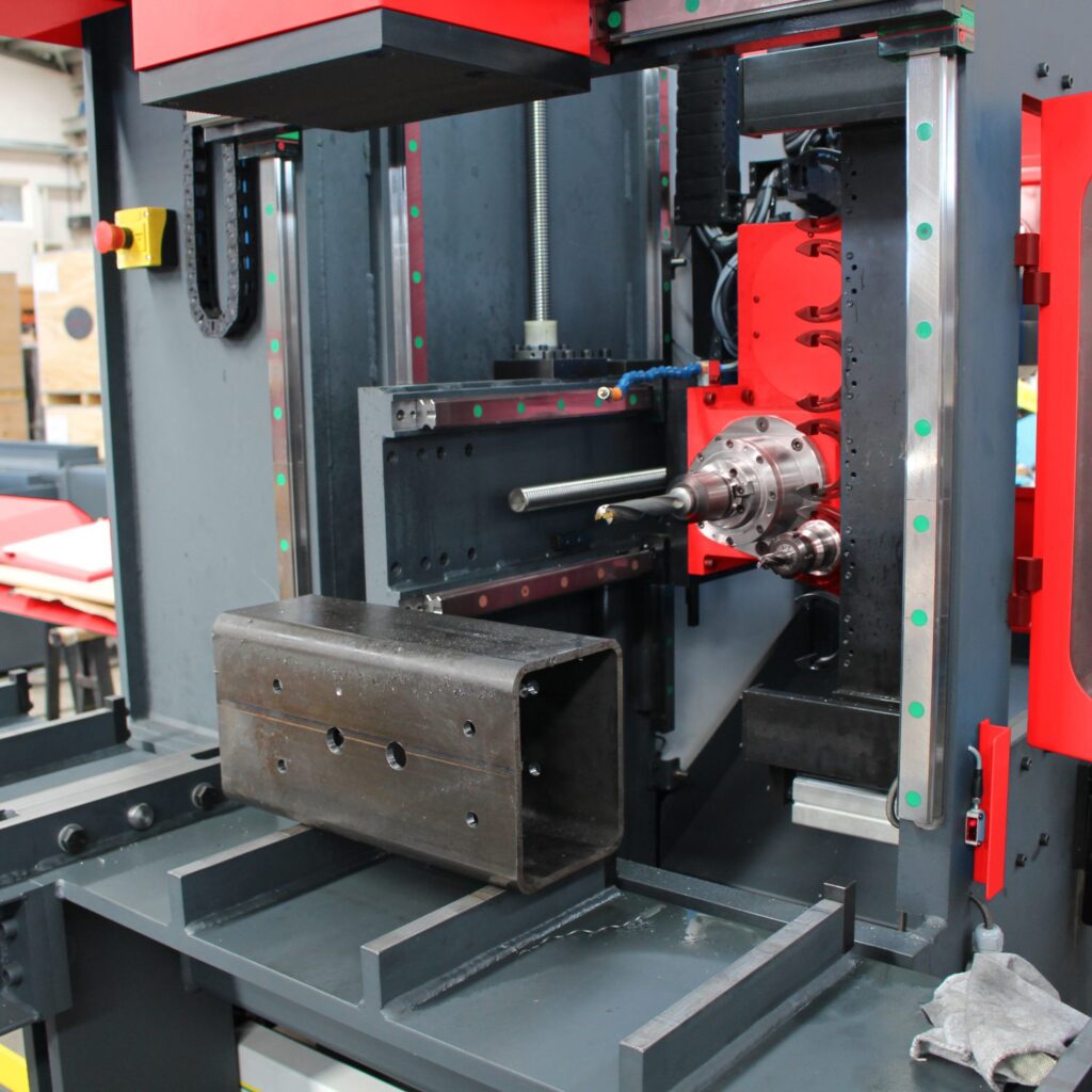
Pendulum mode allows more than one part to run at a time. While the machine runs on one end, the operator can be on the other, refixturing the next part. This process allows the machine never to stop running and eliminates downtime for the operator. The laser scanners also prevent operator injury by slowing down the gantry or stopping in altogether when someone gets too close.
The motion control system on the FlexCNC is the most state of the art controller available, giving the user the capability and flexibility for most machining applications, big and small. The FlexCNC controller is easy to use and is comparable to standard commercially available controllers like the Fanic31i
For more information on the FlexCNC Vertical Machining Center and its features, visit https://flexmachinetools.com/flexcnc/.
When it comes to choosing between a pneumatic, electric, and hydraulic tapping arm, the decision depends on several factors, including the specific application requirements, production volume, and budget. Here are some key considerations to help you choose the right...
Read MoreThe FlexArm engineering team recently designed a custom solution to counterbalance an Aircat 1994 1″ Superduty Impact Wrench. The tool has a weight of 35 lbs and needs the freedom to rotate about the vertical and horizontal axes, as...
Read MoreIn industrial applications, torque reaction arms play a critical role in maintaining worker safety, improving productivity, and reducing workplace injuries. An end user came to us looking for an ergonomic solution for an Atlas Copco ETV-ST101-370-FS-F Nut Runner. The...
Read More
HP |
Max RPM |
FT/LBS |
Series |
---|---|---|---|
18 |
4000 |
92 |
C-20-02 / C-10-02 |
18 |
6000 |
61 |
C-20-02 / C-10-02 |
33 |
12000 |
61 |
CM-20-02 |
Auto Stand-Off – This is currently defined to be surface stand-off and not to be confused with vector stand-off in 5-axis mode. The current auto stand-off is based on a changing surface and will adjust vertically based on the angle of the “A” Axis, so there is five (5) axis taken into account during the calculations, but this is not the same as the tool vector stand-off. There is the ability to do the vector stand-off change while the machine is running manually with buttons on the screen.
Z-Reader Probe – The Z-Reader is a device for mapping the location of the surface. It can be controlled manually & programmatically. The option is NOT active while cutting & is retracted out of harm’s way. It can be triggered to verify the surface at every pierce before the cutting process starts, or it could be used to drive surface mapping of the whole part before cutting starts. It begins with initialization or zeroing of the device to the surface at the beginning of a program and then accumulates or tracks the difference from that zeroing effort.
Automatic Edge Finder – The edge finder is or can be utilized manually (Jogging Method & Screen Buttons), programmatically (M & G codes), or fully automatic routine (dedicated program). This option sets offsets & program rotation to match the orientation & location on the cutting table.
AC Unit Installed on Electrical Cabinet – The unit is mounted on the cabinet’s High Power (480v) side. It is close to the location where the drives are mounted. This option keeps the cabinet temperature stable and allows heat dissipation faster. The servo drives for all axes are the most significant contributors to heat inside the electrical cabinet.
5-Axis Renishaw Calibration – The calibration unit is a Renishaw model APCA45 with a modified spherical stylus. The device has a retractable cover and air purge to clear debris & dust during the activation process. It mounts to a swing arm controlled by a pneumatic rotary, so it is out of the way during regular operation and swings into the calibration position for calibration only.
HP |
Max RPM |
FT/LBS |
Series |
---|---|---|---|
18 |
4000 |
92 |
G-20-06 / G-10-06 |
18 |
6000 |
61 |
G-20-06 / -10-06 |
40 |
4000 |
217 |
GM-20-06 / G-20-06 / G-10-06 |
40 |
6000 |
145 |
G-20-06 / G-20-06 / G-10-06 |