
- FlexCNC
- C-Series FlexCNC
- G-Series FlexCNC
- FlexCare+
- FlexBEAM CNC Structural Machining
- FlexBeam CNC
- FlexJet Waterjet Solution
- FL-Series
- F-Series
- FLX-Series
- FlexArm
- Tapping Arms
- Tables, Accs. & Tap Holders
- Taps & Accessories Store
- Die Grinding Arms
- Drilling Arms
 FlexErgo
- Torque Reaction Arms
- Balance Arms
- Part Manipulator Arms
For service please call
1-800-837-2503 or
Request Service Here
Accelerate ROI with Pendulum Mode
What is Pendulum Mode?
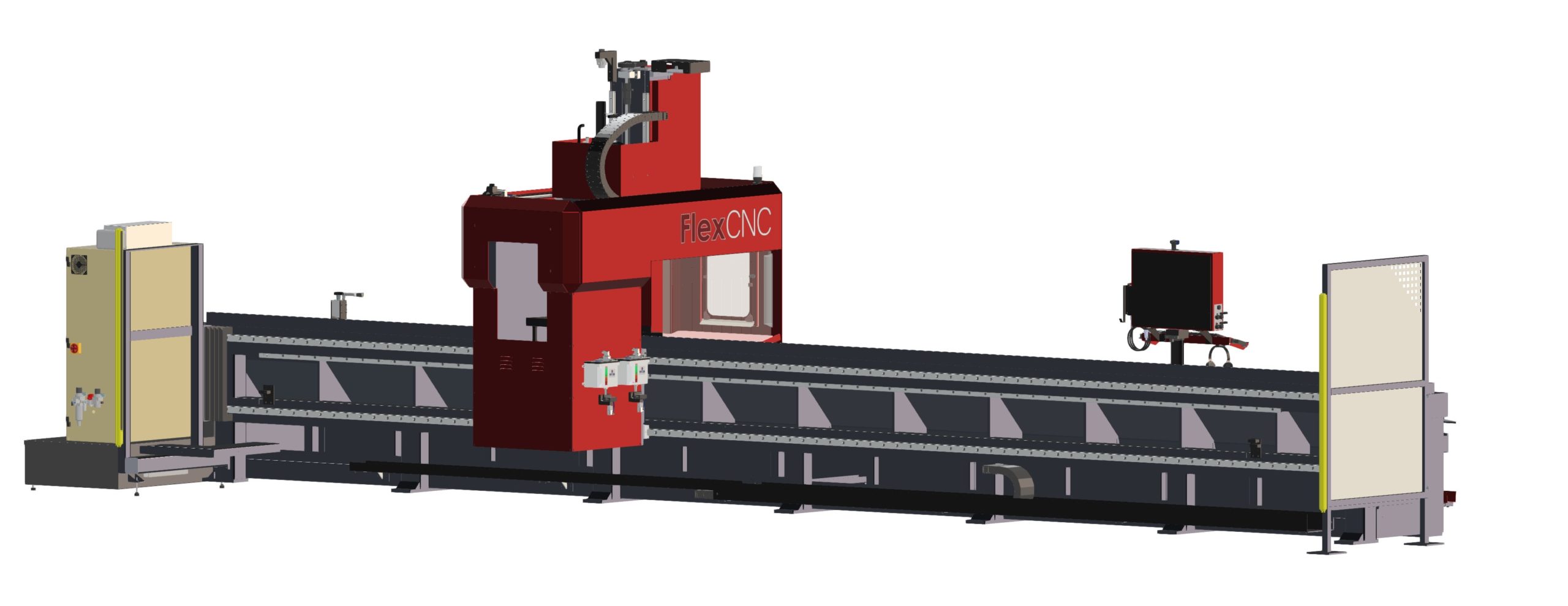
Pendulum Mode is a feature on the FlexCNC that eliminates spindle downtime increasing your overall efficiency. Some of you may know that the FlexCNC is known for its ability to process large parts. However, you may not know that you can efficiently machine smaller parts and various setups using Pendulum Mode.
How Does Pendulum Work?
You can utilize Pendulum Mode using one of two methods. Both will help you decrease operator downtime and increase your spindle uptime. The first method is the back-and-forth style.
Method 1: Back-and-Forth
With this style, an operator sets up parts on opposite ends of the machine bed. While the machining center processes a part on one side of the machine, the operator removes or sets up a part on the other side. Once the machine finishes the first part, the program moves the gantry to the opposite end of the table to process the next part. The operator can change the first setup to a new part preparing for the next machine cycle. This method creates a continuous workflow, accelerating ROI and maximizing throughput.
Method 2: Following the Spindle
The second method to utilize Pendulum Mode is a style we call “following the spindle.” Similar to the back-and-forth technique, this method allows you to follow or chase the machining center as it completes each part. Much like the back-and-forth technique, this keeps the operator, spindle, and process moving.
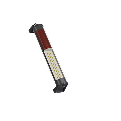
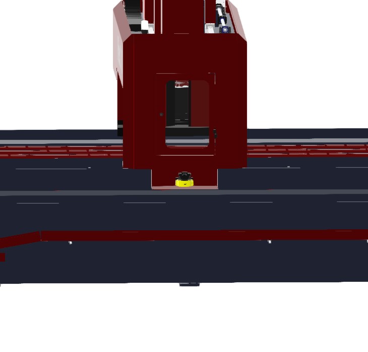
To accomplish maximum spindle uptime, the FlexCNC includes safety laser scanners (standard in both C-Series and G-Series) to ensure the operator stays safe while setting up and replacing parts. If the operator breaks this barrier at any time, the machine spindle will stop (demonstrated in the video below).
Why Use Pendulum Mode?
The reason for setting up parts to run in Pendulum Mode is simple, ROI. If you can keep your spindle moving, your operators will be more productive, and you will have greater throughput resulting in maximum ROI. The machine will pay for itself.
If you want to increase productivity and ROI, consider FlexCNC. To would learn more about how FlexCNC could benefit you and your operations, contact us. We would be happy to do a time study or run a demo on your parts.
See How Pendulum Mode Works
Related Topics
Flex Machine Tools Partners with IGEMS to Elevate Waterjet Cutting Technology in North America
FlexJet powered by IGEMS CNC and CAD/CAM software is a collaboration between Ohio-based Flex Machine Tools and IGEMS of Sweden. The FlexJet will be integrated with the IGEMS CNC and its 5-axis waterjet cutting head known as the “Tilter”....
Read MoreSaving Money By Rescuing Damaged Threads
In the world of metalworking, precision and efficiency are paramount. Threading holes accurately and consistently is essential for ensuring the integrity and performance of manufactured components. However, even the most skilled machinists can encounter challenges, such as damaged or...
Read MoreFlex Machine Tools Launches New FlexJet FLX Waterjet Cutting System
Flex Machine Tools is excited to announce the launch of its newest waterjet cutting system, the FlexJet FLX. This innovative machine is designed to meet the demands of even the most discerning manufacturers, offering superior performance, service, and innovation....
Read More