Pendulum Mode is a feature on the FlexCNC that allows you to run multiple parts at a time. While the machine is running on one end, you can be down on the other end refixturing your next part. This allows the spindle to never stop moving while also eliminating downtime for your operator. Pair that with the custom length beds of the FlexCNC and the possibilities for your setup are endless!
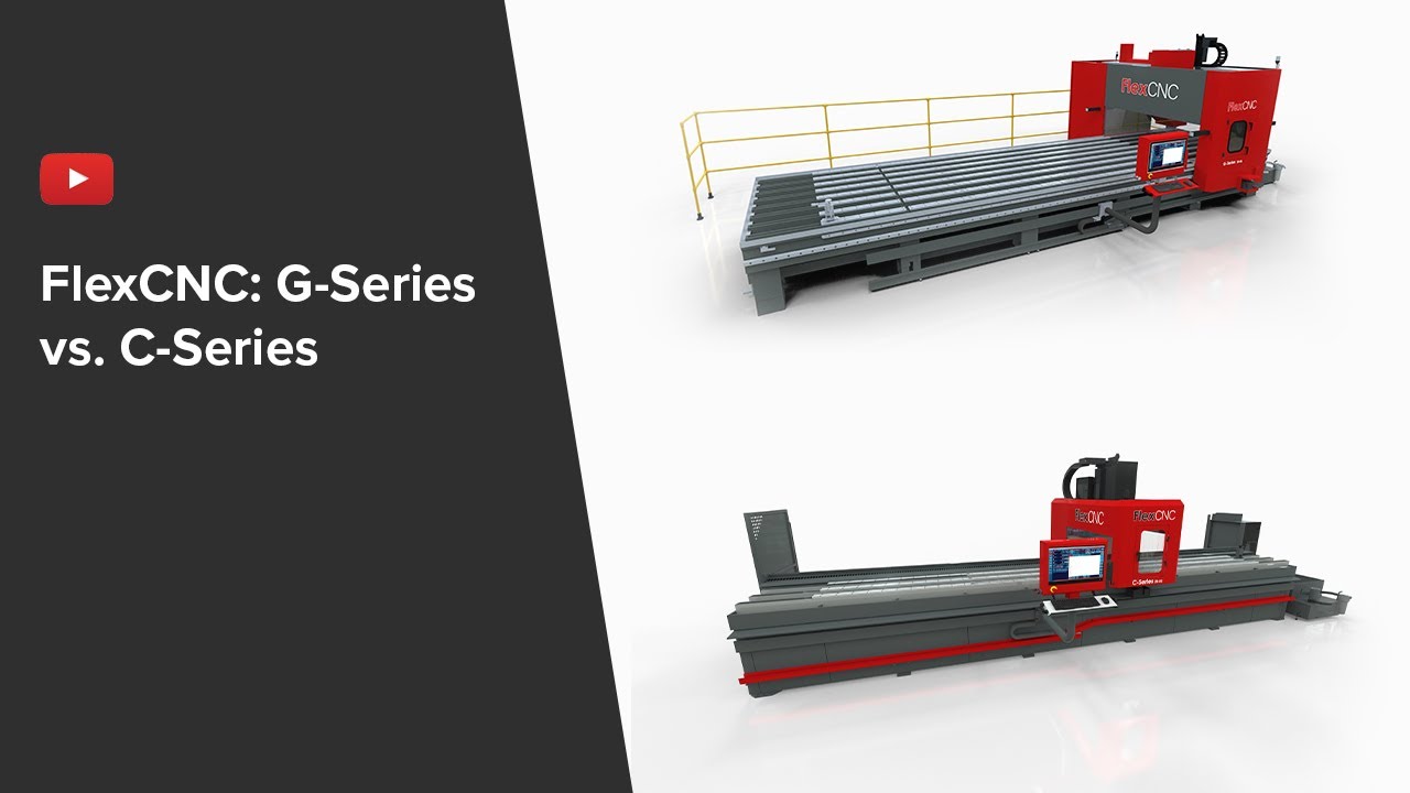
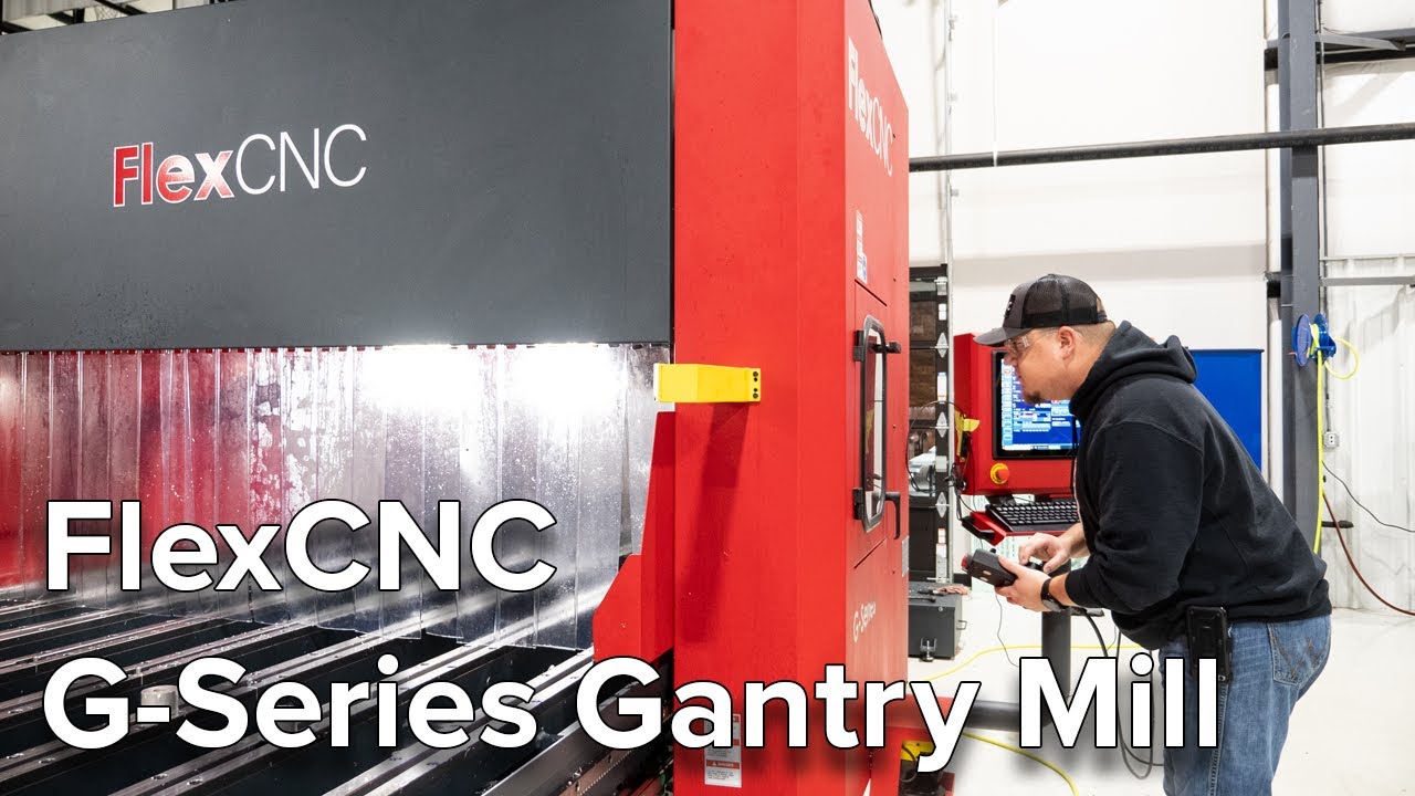
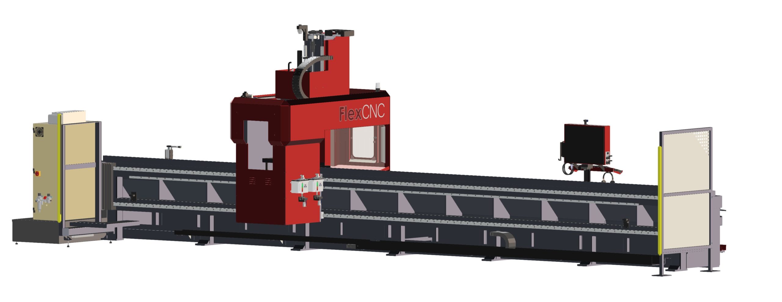
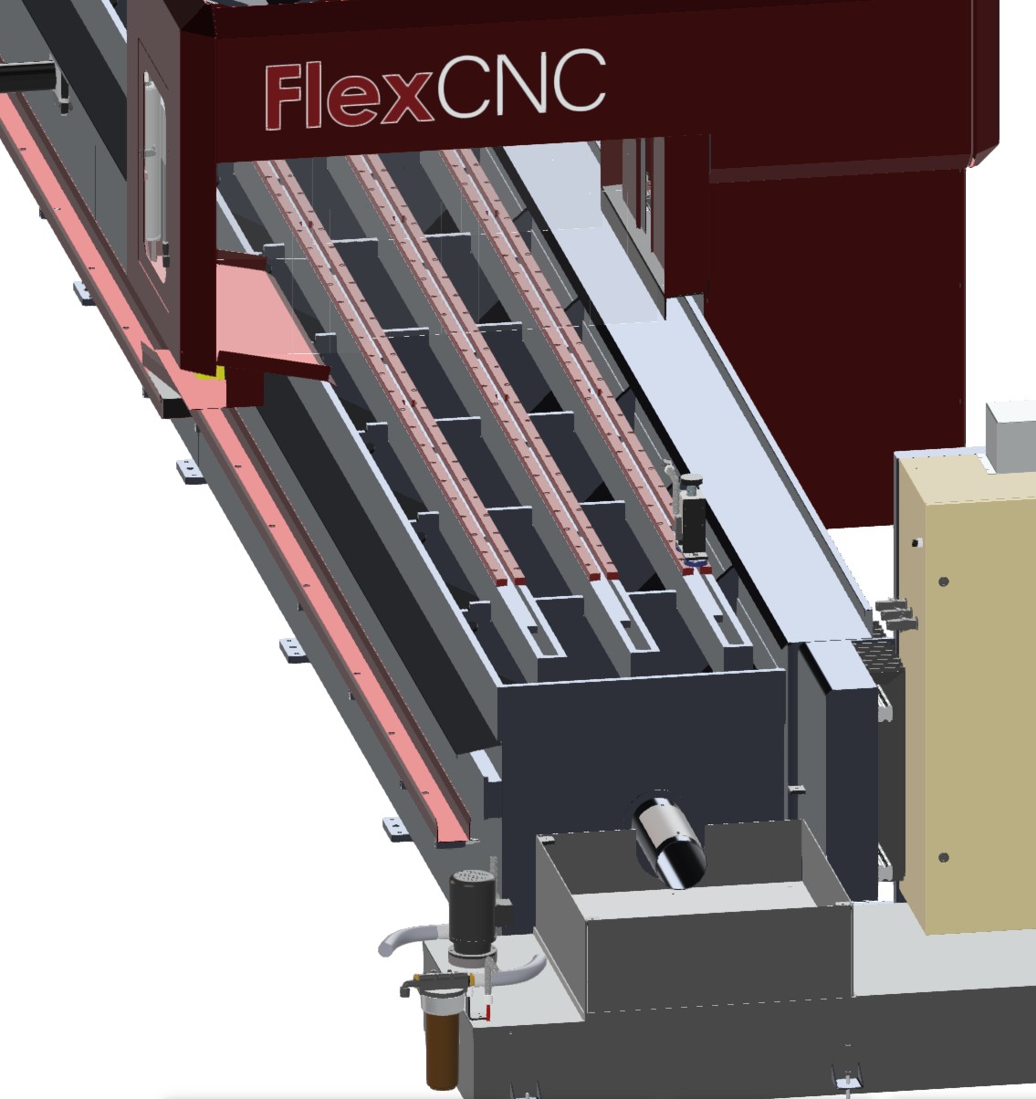
This video is an overview video of the FlexCNC G-Series 20-06. In this video you'll see key features of the FlexCNC G-Series such as FlexCNC controller and hand pendant, precision ball screw positioning through, helical rack and pinion, and more.
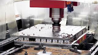
In this video we show a series of videos dedicated to the FlexCNC vertical machining center.
Flex Machine Tools is a leader in manufacturing exploration. We are working to build innovative and high performing machine tool solutions with the lowest possible prices.
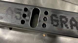
A potential customer came to us interested in the FlexCNC, but first, they wanted to see how the FlexCNC handled their parts. They sent in some laser-cut A527 Grade 50 Steel pieces to test out. The parts required a 45-degree bevel on two sides and drilled holes on the top. The end-user wanted to test their current 20mm chamfer mill on the FlexCNC. For the drilled holes, we selected the reliable 45 mm 4TEX® Drill from Allied Machine & Engineering.
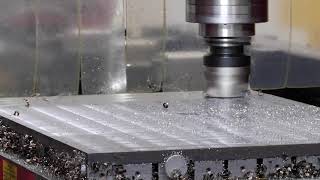
Milling
The machining process presented a challenge because the pieces of material are cut to size using a laser, creating a heat-affected zone around the perimeter of the part. In the first cut, we tried to climb mill down the side of the part, which resulted in chatter and vibration due to the insert aggressively engaging into the hard surface of the heat-affected zone.
Next, we tried conventional milling; this milling style engages the surface at a more forgiving rate, allowing it to get up underneath the heat-affected area and into the material, resulting in a smoother, less restricted cut. Switching from climb milling to conventional milling allowed us to increase the speeds and feeds to the optimum parameters.
Drilling
For the drilling, we opted for a 45 mm 4TEX® Drill from Allied Machine & Engineering. This is our go-to drill for drilling larger holes on the FlexCNC because it is an efficient tool that creates quality holes with an excellent surface finish. The FlexCNC paired with the 4TEX® Drill had no issues getting through the structural steel.
With this demo, we were able to show the end-user the functionality and the capabilities of the FlexCNC. If you think the FlexCNC may be the right solution for your application, let us know, we would be happy to do a demo on your parts for you. Request a demo today.
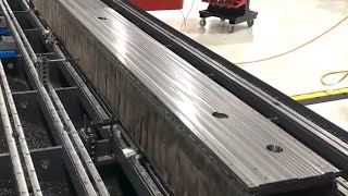
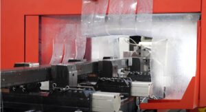
This steel weldment being machined on the FlexCNC will be used as the X-Axis beam for the FlexJet. The operations include facing, peck drilling (100 holes) and end milling.
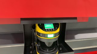
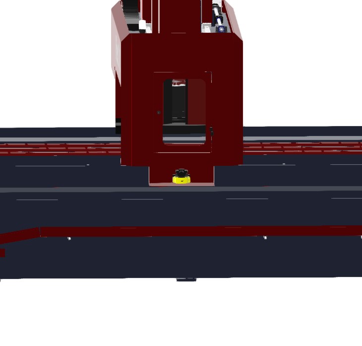
The laser scanner is one of the best safety features on the FlexCNC. It uses proximity sensors that will slow the gantry down and stop completely if your operator gets too close. This feature is great to have especially when using the machine in pendulum mode
Do more with the FlexCNC! Drilling and milling are basic - something any vertical machining center can do. BUT when you had in the custom length beds, 4th axis, and pendulum mode to eliminate any downtime, your throughput will skyrocket!
The 4th axis on the FlexCNC is used to index long pipe or tube eliminating the need to flip and refixture the part. The 4th axis saves on material handling time.
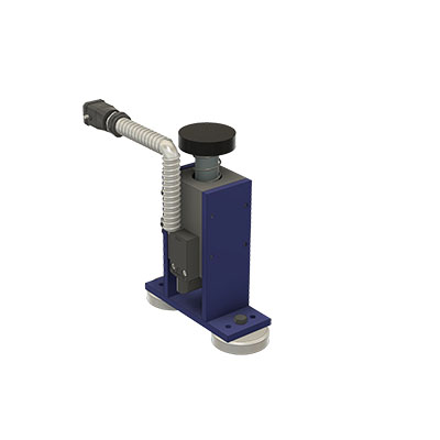
Auto Stand-Off – This is currently defined to be surface stand-off and not to be confused with vector stand-off in 5-axis mode. The current auto stand-off is based on a changing surface and will adjust vertically based on the angle of the “A” Axis, so there is five (5) axis taken into account during the calculations, but this is not the same as the tool vector stand-off. There is the ability to do the vector stand-off change while the machine is running manually with buttons on the screen.
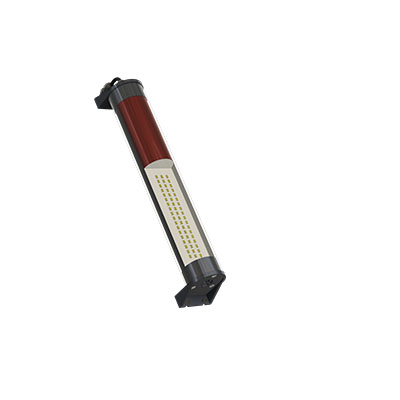
Z-Reader Probe – The Z-Reader is a device for mapping the location of the surface. It can be controlled manually & programmatically. The option is NOT active while cutting & is retracted out of harm’s way. It can be triggered to verify the surface at every pierce before the cutting process starts, or it could be used to drive surface mapping of the whole part before cutting starts. It begins with initialization or zeroing of the device to the surface at the beginning of a program and then accumulates or tracks the difference from that zeroing effort.
Automatic Edge Finder – The edge finder is or can be utilized manually (Jogging Method & Screen Buttons), programmatically (M & G codes), or fully automatic routine (dedicated program). This option sets offsets & program rotation to match the orientation & location on the cutting table.
AC Unit Installed on Electrical Cabinet – The unit is mounted on the cabinet’s High Power (480v) side. It is close to the location where the drives are mounted. This option keeps the cabinet temperature stable and allows heat dissipation faster. The servo drives for all axes are the most significant contributors to heat inside the electrical cabinet.
5-Axis Renishaw Calibration – The calibration unit is a Renishaw model APCA45 with a modified spherical stylus. The device has a retractable cover and air purge to clear debris & dust during the activation process. It mounts to a swing arm controlled by a pneumatic rotary, so it is out of the way during regular operation and swings into the calibration position for calibration only.


