Simple Torque Reaction Solution for an Inline Tool
Watch the video of this application at the bottom of the page.
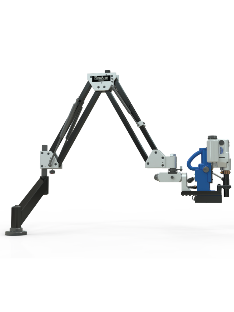
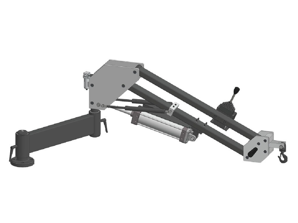
Here is an example of a very simple torque reaction solution. A customer inquired in looking to counterbalance a 25-pound tool with over 497 foot-pounds (625 Newton-meters) of torque. The customer already had a reaction plate, and they wanted to see if we could incorporate this plate into a FlexArm.
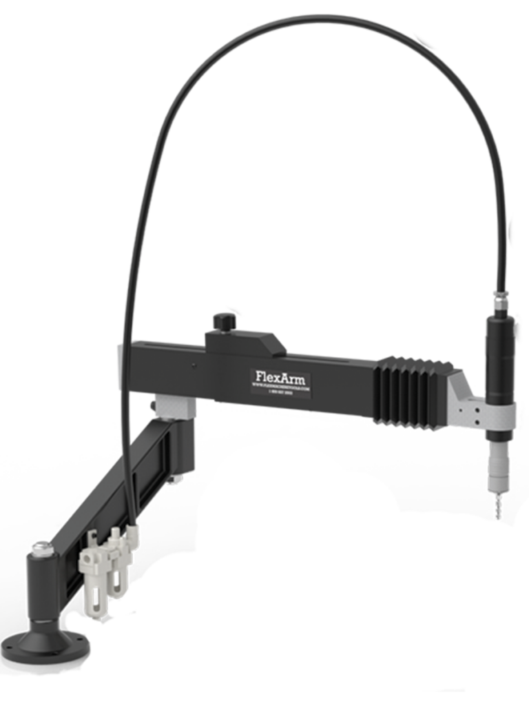
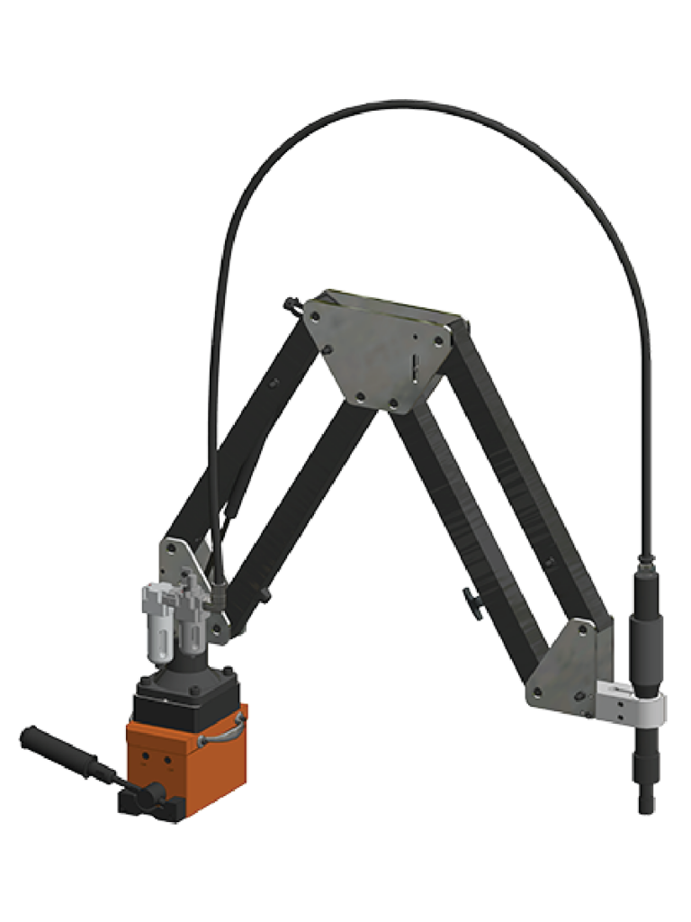
The FlexArm engineers took the reaction plate and integrated it into a custom-designed block on the G-60 torque arm. The customer’s tool was an inline tool operating in a vertical down fastening orientation, so a simple custom block was designed to accept the reaction plate to the underside of the mount.
For custom torque reaction solutions, we normally require the customer to send in the tool, and we create a mount around the tooling. In this case, all we needed was the customer to send in the reaction plate so we could custom fit it to the arm. The reaction plate paired with a FlexArm is a simple solution for anyone looking to counterbalance large amounts of torque.
If you’re looking for a simple or complex torque reaction solution, contact us or give us a call at 1-800-837-2503.
The Problem with Heavy Tools Bolting applications often require heavy tools such as torque wrenches and impact wrenches to achieve the appropriate level of tightness for bolts. However, handling these tools can be challenging and even dangerous. Fortunately, tool...
FlexArm Counterbalances Heavy Aircat Impact Wrench The FlexArm engineering team recently designed a custom solution to counterbalance an Aircat 1994 1″ Superduty Impact Wrench. The tool has a weight of 35 lbs and needs the freedom to rotate about...
In industrial applications, torque reaction arms play a critical role in maintaining worker safety, improving productivity, and reducing workplace injuries. An end user came to us looking for an ergonomic solution for an Atlas Copco ETV-ST101-370-FS-F Nut Runner. The...
Auto Stand-Off – This is currently defined to be surface stand-off and not to be confused with vector stand-off in 5-axis mode. The current auto stand-off is based on a changing surface and will adjust vertically based on the angle of the “A” Axis, so there is five (5) axis taken into account during the calculations, but this is not the same as the tool vector stand-off. There is the ability to do the vector stand-off change while the machine is running manually with buttons on the screen.
Z-Reader Probe – The Z-Reader is a device for mapping the location of the surface. It can be controlled manually & programmatically. The option is NOT active while cutting & is retracted out of harm’s way. It can be triggered to verify the surface at every pierce before the cutting process starts, or it could be used to drive surface mapping of the whole part before cutting starts. It begins with initialization or zeroing of the device to the surface at the beginning of a program and then accumulates or tracks the difference from that zeroing effort.
Automatic Edge Finder – The edge finder is or can be utilized manually (Jogging Method & Screen Buttons), programmatically (M & G codes), or fully automatic routine (dedicated program). This option sets offsets & program rotation to match the orientation & location on the cutting table.
AC Unit Installed on Electrical Cabinet – The unit is mounted on the cabinet’s High Power (480v) side. It is close to the location where the drives are mounted. This option keeps the cabinet temperature stable and allows heat dissipation faster. The servo drives for all axes are the most significant contributors to heat inside the electrical cabinet.
5-Axis Renishaw Calibration – The calibration unit is a Renishaw model APCA45 with a modified spherical stylus. The device has a retractable cover and air purge to clear debris & dust during the activation process. It mounts to a swing arm controlled by a pneumatic rotary, so it is out of the way during regular operation and swings into the calibration position for calibration only.