FlexCNC Time Analysis – Milling Hardened Grinder Blade

Shops are always on the lookout for ways to continually improve the way they operate. Decreasing cycle times and scrap rates can help save costs and allow the business to take on more jobs. These shops can improve cycle times by adjusting speeds and feeds or using specialized tools to dramatically reduce cycle times. This is a worthwhile goal because every minute saved in the machining process has the potential to make the business even more profitable. 

Kline Brothers, a current FlexCNC customer, found a way to improve their cycle times on the FlexCNC read about it below. 

Part Application: 

Hardened Steel for tree stump grinder blades. 
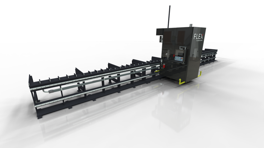
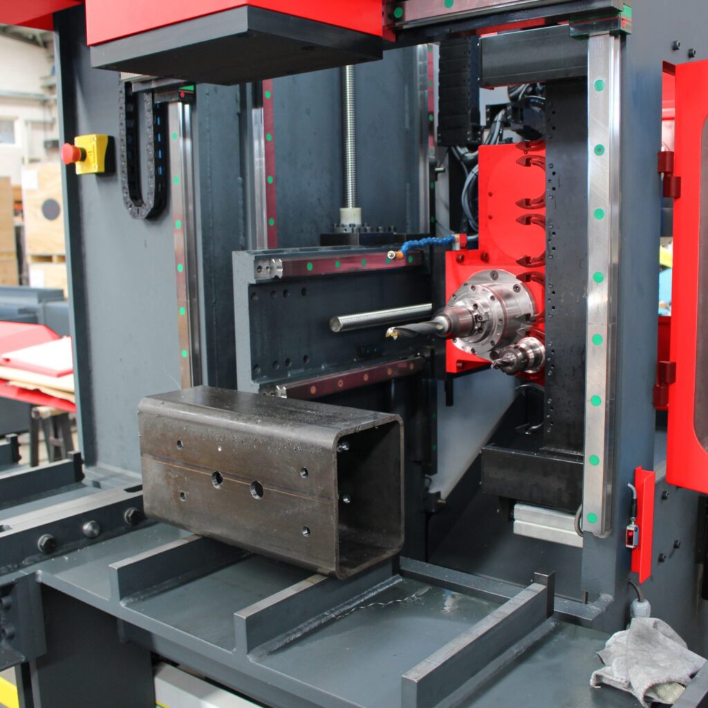
FlexCNC Machining: 

Drill, Mill, & Chamfer

Process:

They started with a low RPM due to the material hardness. They knew this was not going to work because the resulting cycle time was 23 minutes per part. They put in an insert Icar mill and turned the FlexCNC up to 3,995 RPM at 20 in/min, which went through like butter, so they continued to increase the feed. If it would start to chatter, they added more passes, but this allowed them to go even faster. They finished with 130 in/min, reducing their cycle time down to 2 ½ minutes per part. 


Leave a Reply

Your email address will not be published. Required fields are marked *

Standard Features

  • Hand Pendant
  • 22″ Touch Screen Monitor
  • Omron FlexCNC Controller
  • Mobile Control Panel
  • Through Spindle Coolant 
  • Auto Tool Changer 
  • Flood Coolant
HP
Max RPM
FT/LBS
Series

18

4000

92

C-20-02 / C-10-02

18

6000

61

C-20-02 / C-10-02

33

12000

61

CM-20-02

Auto Stand-Off – This is currently defined to be surface stand-off and not to be confused with vector stand-off in 5-axis mode. The current auto stand-off is based on a changing surface and will adjust vertically based on the angle of the “A” Axis, so there is five (5) axis taken into account during the calculations, but this is not the same as the tool vector stand-off. There is the ability to do the vector stand-off change while the machine is running manually with buttons on the screen.

Z-Reader Probe – The Z-Reader is a device for mapping the location of the surface. It can be controlled manually & programmatically. The option is NOT active while cutting & is retracted out of harm’s way. It can be triggered to verify the surface at every pierce before the cutting process starts, or it could be used to drive surface mapping of the whole part before cutting starts. It begins with initialization or zeroing of the device to the surface at the beginning of a program and then accumulates or tracks the difference from that zeroing effort.

Automatic Edge Finder – The edge finder is or can be utilized manually (Jogging Method & Screen Buttons), programmatically (M & G codes), or fully automatic routine (dedicated program). This option sets offsets & program rotation to match the orientation & location on the cutting table.

AC Unit Installed on Electrical Cabinet – The unit is mounted on the cabinet’s High Power (480v) side. It is close to the location where the drives are mounted. This option keeps the cabinet temperature stable and allows heat dissipation faster. The servo drives for all axes are the most significant contributors to heat inside the electrical cabinet.

5-Axis Renishaw CalibrationThe calibration unit is a Renishaw model APCA45 with a modified spherical stylus. The device has a retractable cover and air purge to clear debris & dust during the activation process. It mounts to a swing arm controlled by a pneumatic rotary, so it is out of the way during regular operation and swings into the calibration position for calibration only. 

HP
Max RPM
FT/LBS
Series

18

4000

92

G-20-06 / G-10-06

18

6000

61

G-20-06 / -10-06

40

4000

217

GM-20-06 / G-20-06 / G-10-06

40

6000

145

G-20-06 / G-20-06 / G-10-06