
XYZ: 240″/26″/22″
CT40 Spindle
6000 RPM – 18 HP
ATC x16
*Additional sizes and configurations available
XYZ: 240″/72″/24″
CT50 Spindle
6000 RPM – 40 HP
ATC x20
*Additional sizes and configurations available
Even though quality comes standard, we build each CNC to your specifications to ensure maximum output, lightning fast ROI, and accurate movement. A machine built with your success in mind.
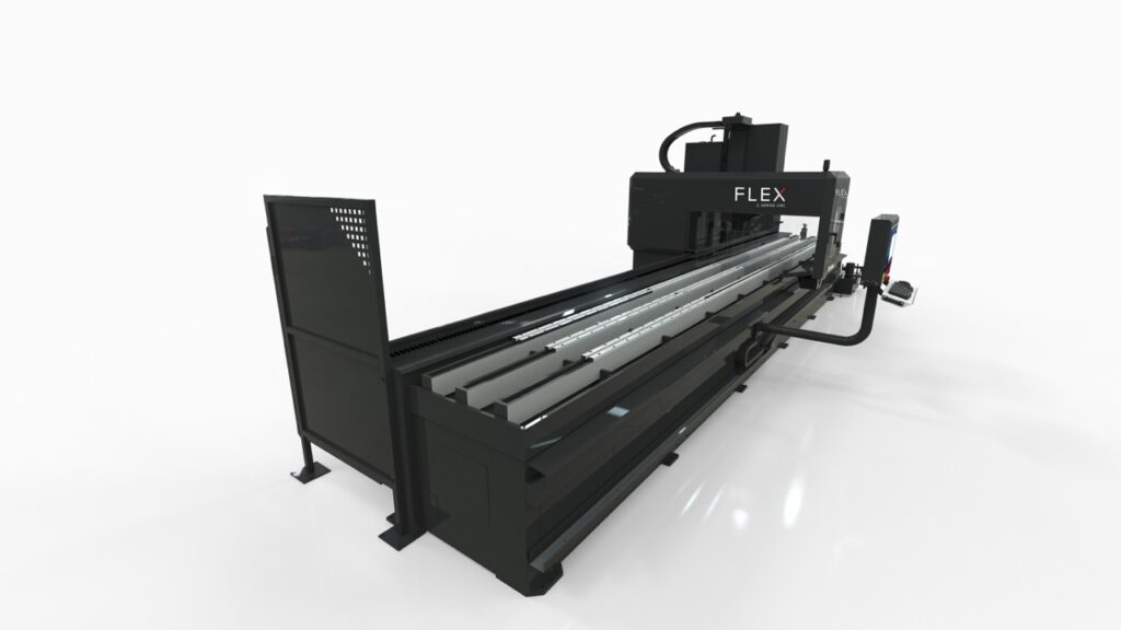
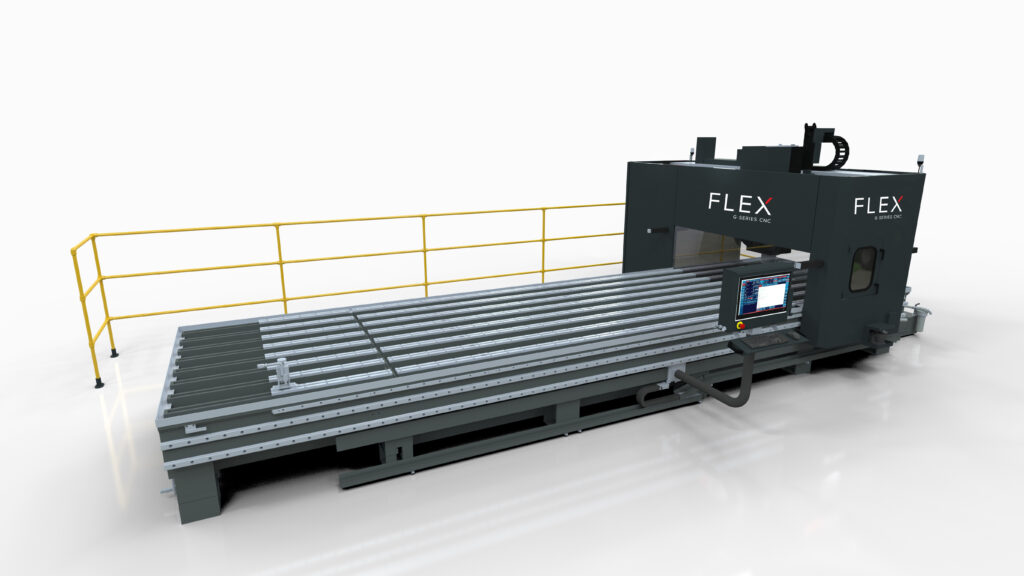
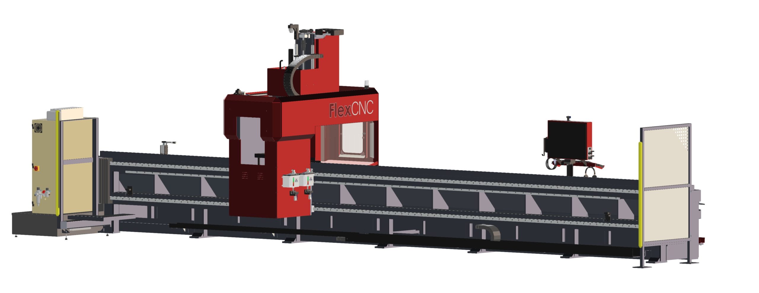
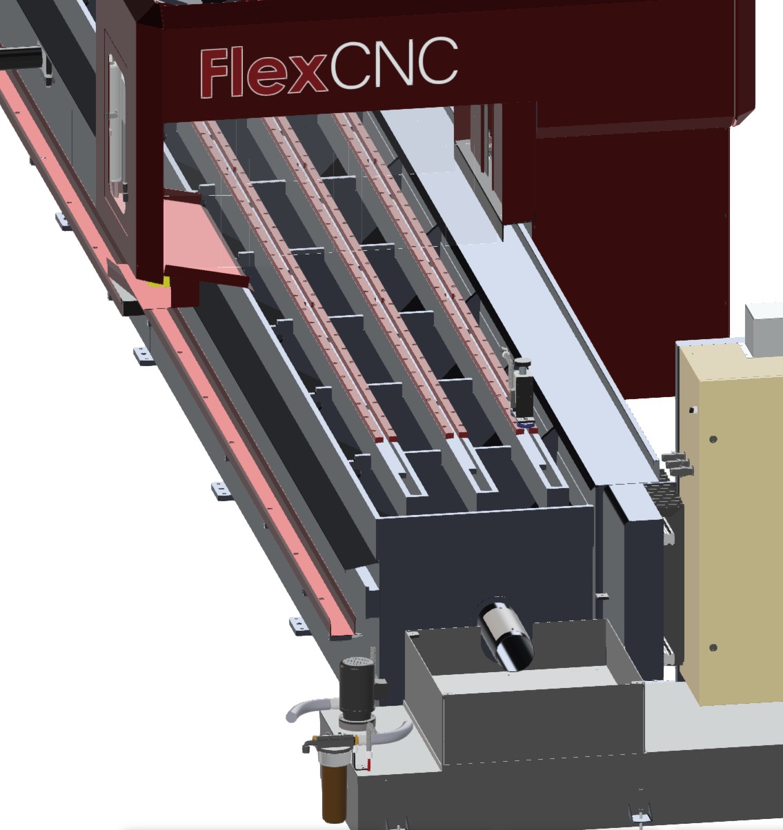
Long parts? Tricky setup? With bed lengths from 10’ – 50’, FlexCNC has the flexibility to accommodate large parts, small parts, and everything in between.
Why hire more labor? Accelerate your productivity with FlexCNC Pendulum Mode. Load and unload your parts without stopping the spindle. Eliminate spindle downtime, increase throughput, and lower your cost per part.
HP |
Max RPM |
FT/LBS |
Series |
|---|---|---|---|
|
18 |
4000 |
92 |
C-20-02 / C-10-02 |
|
18 |
6000 |
61 |
C-20-02 / C-10-02 |
|
33 |
12000 |
61 |
CM-20-02 |
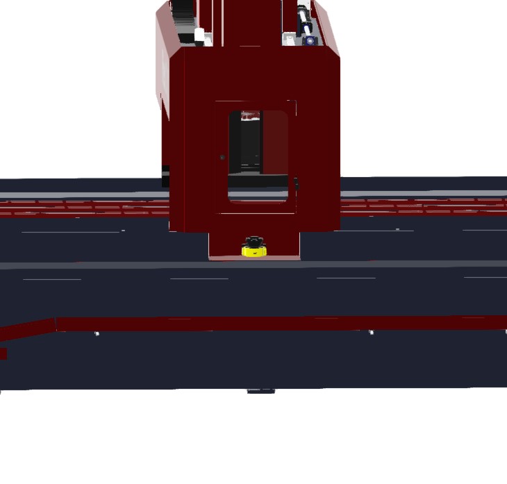
Auto Stand-Off – This is currently defined to be surface stand-off and not to be confused with vector stand-off in 5-axis mode. The current auto stand-off is based on a changing surface and will adjust vertically based on the angle of the “A” Axis, so there is five (5) axis taken into account during the calculations, but this is not the same as the tool vector stand-off. There is the ability to do the vector stand-off change while the machine is running manually with buttons on the screen.
Z-Reader Probe – The Z-Reader is a device for mapping the location of the surface. It can be controlled manually & programmatically. The option is NOT active while cutting & is retracted out of harm’s way. It can be triggered to verify the surface at every pierce before the cutting process starts, or it could be used to drive surface mapping of the whole part before cutting starts. It begins with initialization or zeroing of the device to the surface at the beginning of a program and then accumulates or tracks the difference from that zeroing effort.
Automatic Edge Finder – The edge finder is or can be utilized manually (Jogging Method & Screen Buttons), programmatically (M & G codes), or fully automatic routine (dedicated program). This option sets offsets & program rotation to match the orientation & location on the cutting table.
AC Unit Installed on Electrical Cabinet – The unit is mounted on the cabinet’s High Power (480v) side. It is close to the location where the drives are mounted. This option keeps the cabinet temperature stable and allows heat dissipation faster. The servo drives for all axes are the most significant contributors to heat inside the electrical cabinet.
5-Axis Renishaw Calibration – The calibration unit is a Renishaw model APCA45 with a modified spherical stylus. The device has a retractable cover and air purge to clear debris & dust during the activation process. It mounts to a swing arm controlled by a pneumatic rotary, so it is out of the way during regular operation and swings into the calibration position for calibration only.
HP |
Max RPM |
FT/LBS |
Series |
|---|---|---|---|
|
18 |
4000 |
92 |
G-20-06 / G-10-06 |
|
18 |
6000 |
61 |
G-20-06 / -10-06 |
|
40 |
4000 |
217 |
GM-20-06 / G-20-06 / G-10-06 |
|
40 |
6000 |
145 |
G-20-06 / G-20-06 / G-10-06 |
"The FlexCNC handles some of the most challenging parts faster. Every second saved adds up to hours over the course of a day—and saving time while increasing productivity and accuracy is a no-brainer.”
Felker Bros